Sharper peaks using 2-stage low sample dispersal injection technique
From LEAP
(→For other cost/time saving measures consider:) |
|||
| Line 29: | Line 29: | ||
* Summary of LC Multi Valve Applications [http://www.leapwiki.com/mediawiki/index.php?title=Summary_of_LC_Multi_Valve_Applications] | * Summary of LC Multi Valve Applications [http://www.leapwiki.com/mediawiki/index.php?title=Summary_of_LC_Multi_Valve_Applications] | ||
* LEAP Shell Software and application for custom injections and scheduling [http://www.leaptec.com/software/leap-shell-3.php] | * LEAP Shell Software and application for custom injections and scheduling [http://www.leaptec.com/software/leap-shell-3.php] | ||
| + | ---- | ||
[[Image:LEAP Logo.png|frame|[http://www.leaptec.com leaptec.com]<br />[http://www.leapwiki.com leapwiki.com]]] | [[Image:LEAP Logo.png|frame|[http://www.leaptec.com leaptec.com]<br />[http://www.leapwiki.com leapwiki.com]]] | ||
Revision as of 03:00, 2 June 2009
For low dispersion of the sample (no tailing in the loop), and to meter a very small volume of sample very precisely into the flow, the customer wanted to use the valve to do a " heart cut" of the sample by toggling the injection valve at the same time the syringe is injecting very slowly.
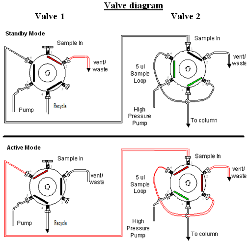
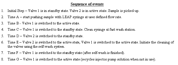
The PAL will function in a manner similar to a UPLC system. The HTS PAL will use two 6-port Cheminert valves to perform this process. An injection will be made to Valve 1. A injector pump will be plumbed up to Valve 1 with a very low flow rate (i.e. 5ul/second). Once the sample is loaded into Valve 1, the loop will switch for an amount of time determined by the operator.
The goal will be to transfer 0.5ul of sample from the syringe to the center of the 5ul loop on Valve 2. To transfer the sample slug correctly, the operator will be able to manipulate three variables. Those variables will be (1) the flow rate of the injector pump, (2) the period of time Valve 1 will be switched to load the sample from the loop to the injector pump flow line, and (3) the amount of time the injector pump will allowed to pump the sample to the 5ul loop of Valve 2. Once the sample is centered in the 5ul loop of Valve 2, the valve will be switched and the sample will be pumped through the column and to the HPLC detector using a LC system.
Additional Reference Material
Powerpoint of customer publication:
Image:Multi-Stage-Injection-in-Fast-LC Hayward Aug2007.pdf
Project Ref: H1103
For other cost/time saving measures consider:
- LEAP offers multiple choices of Valve Self Wash Stations to aid in cleaning the valve [1]
- Dual Channel Serial Injection with Front Cut (M-002) using Analyst and ICC-CE [2]
- Dual Channel Parallel Injection (M-003) using Cycle Composer Software and Analyst [3]
- “Look Ahead”, sample prep before injection (M-004) using LEAP Shell Software [4]
- Dual Channel Parallel Injection (M-005) using LEAP Shell software [5]
- Summary of LC Multi Valve Applications [6]
- LEAP Shell Software and application for custom injections and scheduling [7]
Contact LEAP
For additional information about this technique please contact LEAP Technologies for detailed information


