Monitoring of Polymerization reactions
From LEAP

| Monitoring of Polymerization reactions |
| Application Type | |
| SPECIAL | |
| Application ID | |
| Description | |
| Timed sampling of polymer reactor vessel under high pressure and temperature. |
Contents |
Overview
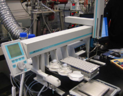
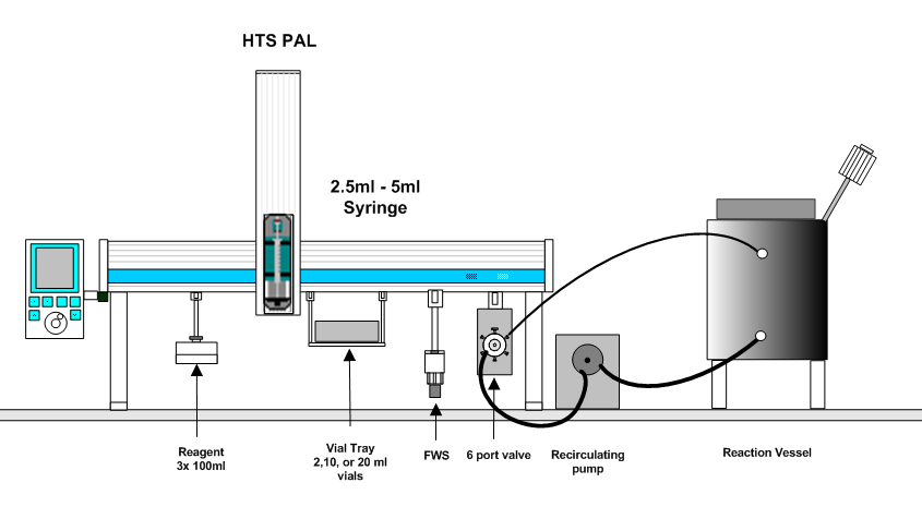
Reaction monitoring of polymers, chemicals, and fermentation broths is a vital part of product development. Often times these reactions are at elevated temperatures and pressures in the presence of catalysts. Reactions can take a couple hours up to a full day to complete. Samples often need quenching to stop the reaction at specific time points. This application is geared toward a cost effective yet reliable way of taking timed samples and quenching each sample with optional just-in-time chemical analysis by either gas or liquid chromatography. One such reaction is the catalytic conversion of a mixture of monomers to a mixture of polymers of specific chain lengths to achieve the properties needed for a specific application. Typical reaction conditions include temperatures of 100 C, pressures of 100 psi, and 18 hour reaction durations. Often very volatile and explosive solvents are involved which presents a very real safety issue when unattended timed samples are taken. It is also important that the sampling does not interfere with the polymeric reaction. LEAP has broken new ground in one such application, where the complexities of this type of reaction monitoring has been fully automated using a PAL workstation equipped with a sampling valve, a gear pump, and timing software to control the whole process.
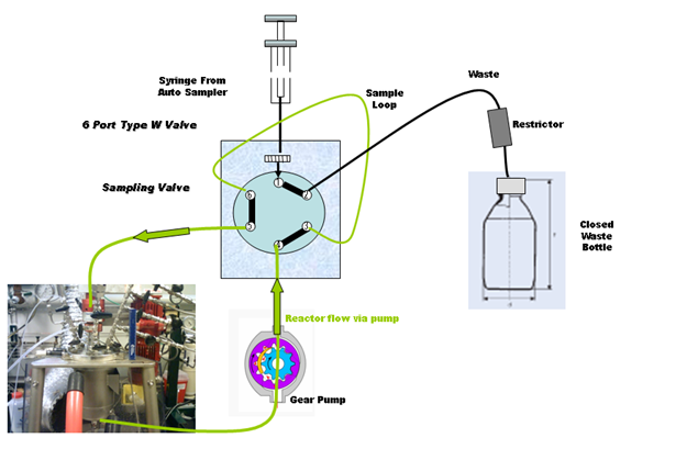
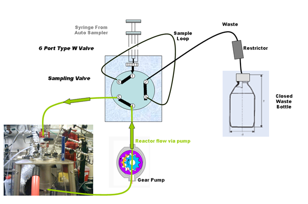
This application uses a re-circulating pump to continuously flow fluid from a reactor vessel to the HPLC valve of the PAL. At specified timed intervals the HPLC valve toggles so that the loop contain the the reaction fluid is taken temporarily out of flow, and the contents of the loop is sampled using a syringe and placed in a storage vial for later analysis.
The whole system can be placed upon a moveable cart and positioned close to any reactor.
Flow Diagram in default position (Loop being flushed):
Flow diagram when sampling from loop:
The waste container with restrictor is to trap expansion liquid/gas in the case where the reaction mixture is under pressure.
Overall System Layout:
Screen Shots
Further Documentation
Contact LEAP
For additional information about this technique please contact LEAP Technologies for detailed information


